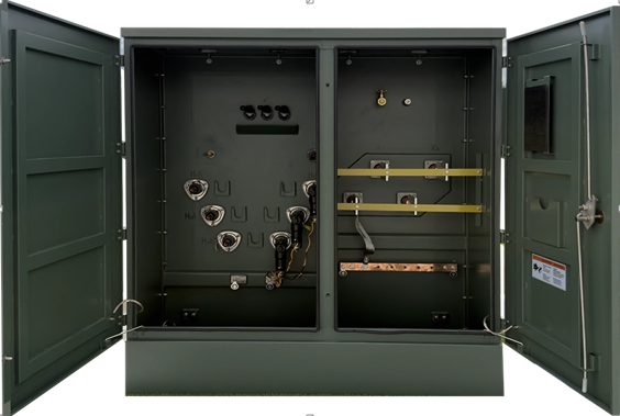
Large electrical projects depend on a reliable power supply, accurate load calculations, and equipment that can handle demanding operating conditions. Industrial facilities, commercial buildings, manufacturing plants, and infrastructure developments often require high-capacity transformers to distribute electricity safely and efficiently. Selecting the right transformer rating at the planning stage helps prevent capacity shortages, unnecessary energy losses, and expensive equipment changes later.
A transformer 3000 kVA unit may suit projects with substantial electrical demand, provided its voltage ratings, load profile, installation conditions, and protection requirements match the application. Understanding these specifications before purchasing equipment allows project managers, electrical engineers, and facility owners to make informed decisions.
What Does a 3000 kVA Transformer Rating Mean?
Kilovolt-amperes (kVA) measure apparent electrical power, which includes both active power used by equipment and reactive power associated with electrical loads. A transformer rated at 3000 kVA can handle up to 3,000 kilovolt-amperes under its specified operating conditions.
The actual usable power in kilowatts depends on the facility’s power factor. For example, at a power factor of 0.90, a 3000 kVA transformer corresponds to approximately 2,700 kW of active power at full rated apparent load.
This distinction matters because industrial equipment, motors, compressors, and other inductive loads can affect power factor. A facility consuming 2,500 kW may require more than 2,500 kVA of transformer capacity, depending on its electrical characteristics.
Engineers should calculate the expected demand in kVA rather than relying solely on the total wattage listed for connected equipment.
See also: Discover the Lifestyle Benefits of Living in Blackheath
Assessing the Project’s Electrical Load
Load assessment should be one of the first tasks in electrical project planning. The transformer must supply the facility’s expected demand without operating beyond its permitted limits.
Start by preparing a load schedule covering machinery, HVAC systems, lighting, production equipment, pumps, lifts, and other electrical devices. Record the rated power, operating voltage, power factor, and expected usage pattern of each major load.
Next, estimate the maximum demand. Not every machine operates at full capacity simultaneously, so applying an appropriate demand factor can produce a more realistic calculation than simply adding every connected load. However, the calculation must account for production peaks, future equipment additions, and simultaneous motor starts.
Consider these factors during the assessment:
- Peak demand: Identify periods when several high-power machines operate together.
- Starting currents: Large motors may draw substantial current during startup, creating temporary voltage dips.
- Power factor: Lower power factors increase the apparent power required to supply a given active load.
- Nonlinear loads: Variable-frequency drives, electronic equipment, and other nonlinear devices may introduce harmonics.
- Expansion plans: Include realistic allowances for planned production lines, additional floors, or new machinery.
A 3000 kVA rating should be selected after these calculations, not simply because the project appears large. An oversized transformer can increase initial expenditure and no-load losses, while an undersized unit may experience excessive loading and reduced operational flexibility.
Voltage Ratings and Transformer Configuration
Transformer capacity is only one part of the specification. Primary and secondary voltage ratings must match the electrical network and the equipment being supplied.
For example, a project might require a medium-voltage primary supply and a low-voltage secondary distribution system. The actual voltage combination depends on the utility connection, local electrical standards, and the facility’s distribution design.
Three-phase transformers are commonly used for industrial and commercial installations because they support large, balanced electrical loads. Engineers must also determine the appropriate winding configuration, vector group, and neutral arrangement.
These details affect grounding, phase relationships, fault behaviour, and compatibility with downstream systems.
Other electrical specifications deserve careful review:
- Frequency: The transformer must be suitable for the supply frequency, typically 50 Hz or 60 Hz depending on the region.
- Impedance: Percentage impedance influences fault current and voltage regulation.
- Insulation level: Insulation must suit the system voltage and expected electrical stresses.
- Tap changer: Off-circuit or on-load tap changing may be required to accommodate supply-voltage variations.
- Short-circuit withstand capability: The design must withstand the mechanical and thermal stresses associated with specified fault conditions.
These ratings should be documented in the technical specification before quotations are compared.
Choosing Between Oil-Filled and Dry-Type Designs
The installation environment often determines which transformer construction is most suitable. Oil-filled and dry-type transformers each have characteristics that make them appropriate for different projects.
Oil-filled transformers use insulating liquid for electrical insulation and heat transfer. They are widely used in substations, outdoor installations, and industrial power systems. Their suitability depends on the cooling arrangement, environmental conditions, fire precautions, and maintenance requirements.
Dry-type transformers use solid insulation systems and rely on air or another approved cooling arrangement. They may be suitable for indoor installations such as commercial buildings, hospitals, factories, and facilities where managing insulating liquid would be inconvenient.
The choice should consider more than the purchase price. Engineers need to examine ventilation, fire protection, available floor space, environmental risks, noise restrictions, and maintenance access.
A 3000 kVA transformer can be a substantial piece of equipment, so its dimensions, total weight, access routes, foundation requirements, and lifting arrangements must be checked against the site layout.
Cooling, Efficiency, and Operating Temperature
Heat management directly affects transformer performance and service life. Electrical losses occur in the windings and magnetic core, and these losses generate heat during operation.
Transformer cooling systems are designed to keep temperatures within specified limits. Depending on the design, cooling may use natural air circulation, forced air, natural oil circulation, or forced oil circulation.
Project engineers should review the manufacturer’s rated losses, cooling classification, temperature-rise limits, and permitted operating conditions. Ambient temperature and altitude can affect cooling performance, so equipment intended for a hot climate or a high-altitude site may require specific design provisions or derating.
Efficiency deserves attention throughout the equipment selection process. Even a modest difference in losses can influence lifetime operating costs when the transformer runs continuously.
For an accurate comparison, evaluate both no-load losses and load losses. No-load losses occur whenever the transformer is energised, while load losses generally increase with the current flowing through its windings.
A transformer with a lower initial price may cost more to operate over many years. Comparing purchase cost, expected loading, energy prices, and projected operating hours gives decision-makers a clearer picture of total ownership cost.
Protection Systems and Electrical Safety
A large transformer requires coordinated protection to limit damage during faults and abnormal operating conditions. Protection design should be developed alongside the distribution system rather than added after equipment selection.
Depending on the installation, the protection scheme may include overcurrent relays, earth-fault protection, differential protection, temperature monitoring, surge arresters, and suitable circuit breakers. Oil-filled units may also require specific pressure, gas, or oil-temperature protection features appropriate to their construction.
Protective devices must be coordinated with upstream utility equipment and downstream distribution boards. Engineers should calculate prospective short-circuit currents and confirm that switchgear, busbars, cables, and protective devices have adequate ratings.
Earthing arrangements also require careful design. The transformer tank, associated metalwork, neutral point where applicable, and other exposed conductive parts must be connected according to the approved grounding scheme and applicable regulations.
Commissioning tests should verify insulation condition, winding resistance, turns ratio, protection operation, and other tests specified by the manufacturer and project standards. Qualified personnel should complete the installation and testing before the transformer is energised.
Installation Planning and Maintenance Access
A successful installation depends on practical site preparation as much as electrical design. The transformer foundation must support the equipment’s operating weight and comply with structural requirements. Outdoor installations may need drainage, weather protection, fencing, and suitable clearance from nearby structures.
Indoor projects require adequate ventilation, access for inspection, and appropriate fire-safety provisions. Cable trenches, bus ducts, switchgear locations, and incoming supply routes should be coordinated early to avoid costly modifications during construction.
Maintenance planning should cover routine inspections, temperature monitoring, cleaning, connection checks, and testing at intervals recommended by the manufacturer and applicable standards. Oil-filled units may require oil sampling and condition analysis, while dry-type units may need periodic cleaning and inspection of insulation and cooling passages.
Maintaining accurate records of operating temperatures, loading, test results, and maintenance activities can help identify developing faults before they cause unplanned outages.
Preparing a Clear Transformer Specification
Before requesting quotations, prepare a specification that describes the electrical and physical requirements of the project. Include the 3000 kVA rating, primary and secondary voltages, frequency, phase configuration, cooling method, impedance, insulation requirements, tap-changing arrangement, and expected environmental conditions.
The document should also state applicable standards, efficiency requirements, protection expectations, noise limits, installation location, testing requirements, and documentation needed for approval.
Ask suppliers to provide guaranteed loss figures, dimensional drawings, connection diagrams, technical data sheets, and details of warranty coverage and after-sales support. Comparing offers against the same specification makes differences in equipment quality, operating costs, and installation requirements easier to identify.
A well-planned transformer installation begins with a realistic understanding of demand and ends with equipment that fits the electrical network, site conditions, and long-term operating needs. Careful specification and professional engineering review help ensure that the selected transformer can support the project reliably from commissioning through years of service.